

A lot of UAV work starts the same way student FSAE and small aerospace programs start: someone has a frame, an arm, a payload bay, or a landing-gear casting — and a blank PDM vault. Reverse engineering is how you get into drones without waiting on OEM files that will never arrive.
We scan the hardware (lab structured light, and aerial photogrammetry when the airframe is the object) and return the model type you can use: mesh for packaging, surfaces for aero, or feature-based CAD for mounts, booms, and drawings.
Who this is for
- Builders and startups standing up a UAV or small-aircraft program
- Aerospace teams that need as-built interfaces for payloads and avionics
- Educators and competition teams who need CAD of a donated airframe
- Shops that will machine or 3D-print the next revision, not just look at an STL
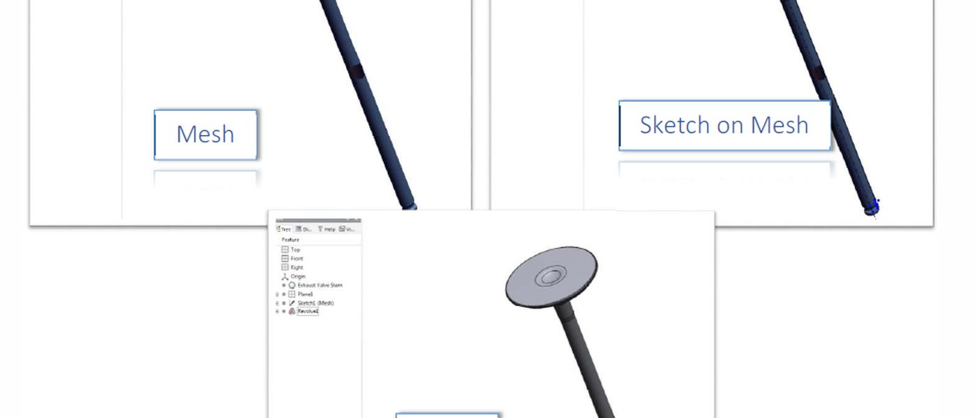
The reverse engineering deliverable list still applies: mesh, NURBS, solids, or hybrid. A carbon boom is not modeled the same way as a machined motor mount. Tell us the manufacturing step.
Same lab, new vehicle class
Bolton Works has been in aero geometry for years — spars, engine hardware, turbomachinery. UAV airframes are a continuation: lighter materials, faster iteration, the same need for honest scale. If you are getting into drones and need drawings, start with photos of the airframe.
— Bolton Works